
Mega Fix Up
Atari / Nintendo specific

I have been to see the adopted fams in Yorkshire over the Easter weekend. We visited some nice video game shops (Sore Thumb Retro Games in York and Electric Town in Castleford) We also had an evening at Arcade Club Leeds
I left home with a box full of stuff for the Yorkshire gang and came back with my box fuller than when I left Glasgow.
Full of stuff to tinker with, no less.
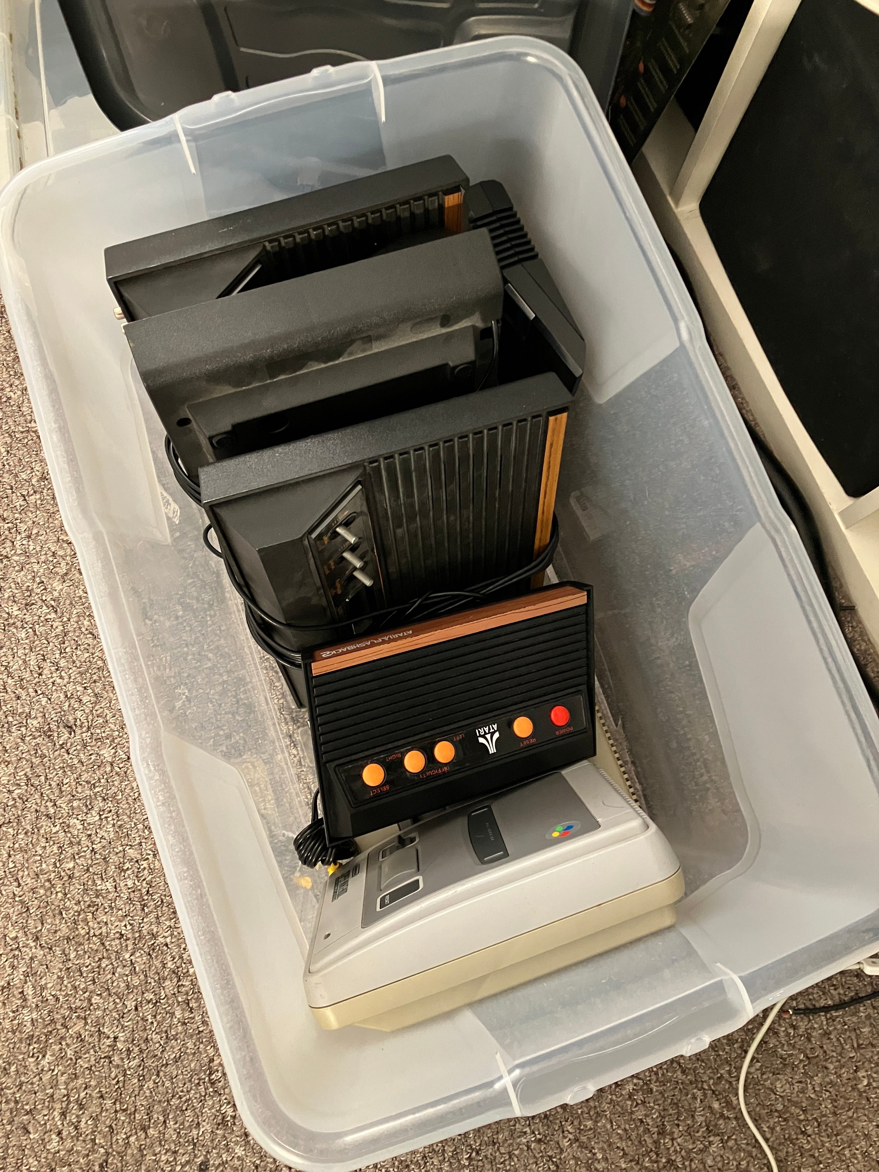
Here is the offending box of goodies (minus the first item I’ll be tinkering with) The SNES console in the box is just an empty shell. I’ll be using half of it to make a slightly nicer SNES.
Item One - SNES requiring some TLC
(and a two switch region mod)
This tinkering begins with a quick back story. I actually bought something from Sore Thumb Retro Games. I got myself a copy of SNES Dr. Mario. It’s a game I really enjoy and I sort of collect the different versions now. I already have the Japanese and European Gameboy and Famicom versions. I have also just bought the European NES cartridge from the popular online electronic auction site. Problem is, I have a Super Famicom Jr, the later released Japanese console and they are region locked. This PAL SNES cart simply won’t work on it - we tried back in Bobbi and Lynn’s testing conservatory. We also had to fix his region modded SNES as it wasn’t reading cartridges at all. A good clean out of the cartridge port with Servisol spray and my spittle infused breath (blowing down cartridge slot and cartridge pins helped with a tightening down of the cartridge socket inside the SNES. We successfully managed to test the cartridge but it was reporting that the game couldn’t be played on that region machine. Ho hum, at least the game was functional.
I mentioned this to our pal Gaz, who being an upstanding gentleman as well as a top bendy yellow fruit, brought along a half modified SNES and a donor case for me to make up a multi region console for myself. All of this, so I didn’t have to take a soldering iron, drill and other torture tools to my unblemished Super Famicom Jr.
I found a guide to do this in the form of a Tube of You videogram. For some reason, my go-to modding site mmmonkey isn’t online anymore and the website is now an adult dating website…
Here is the tidied up and completed wiring. The mod requires you to unsolder and lift a single very small SMD pin from three seperate ICs. You then join two together to a point on a switch. The switch is wired to the console’s +5VDC and GND points and the CIC chip is also wired to a second switch. One switch enables the console to play either European PAL and Japanese or American NTSC games. The second switch enables 50 or 60hz refresh rates. Using 60hz removes the annoying top and bottom PAL orders on the game image. The games also run at the correct speed. We PAL consumers got slightly slower games back in the day [sad emoji]
I also sneaked in a blue LED rather than the standard red one, to show it was special. I think the dirty great switches on the side of it are a bit of a giveaway…


I have since made up some Dymo labels to show the switch settings and given the case a spit ‘n’ polish.
Tinkering One complete.
Item Two - Atari 2600 Fail #1
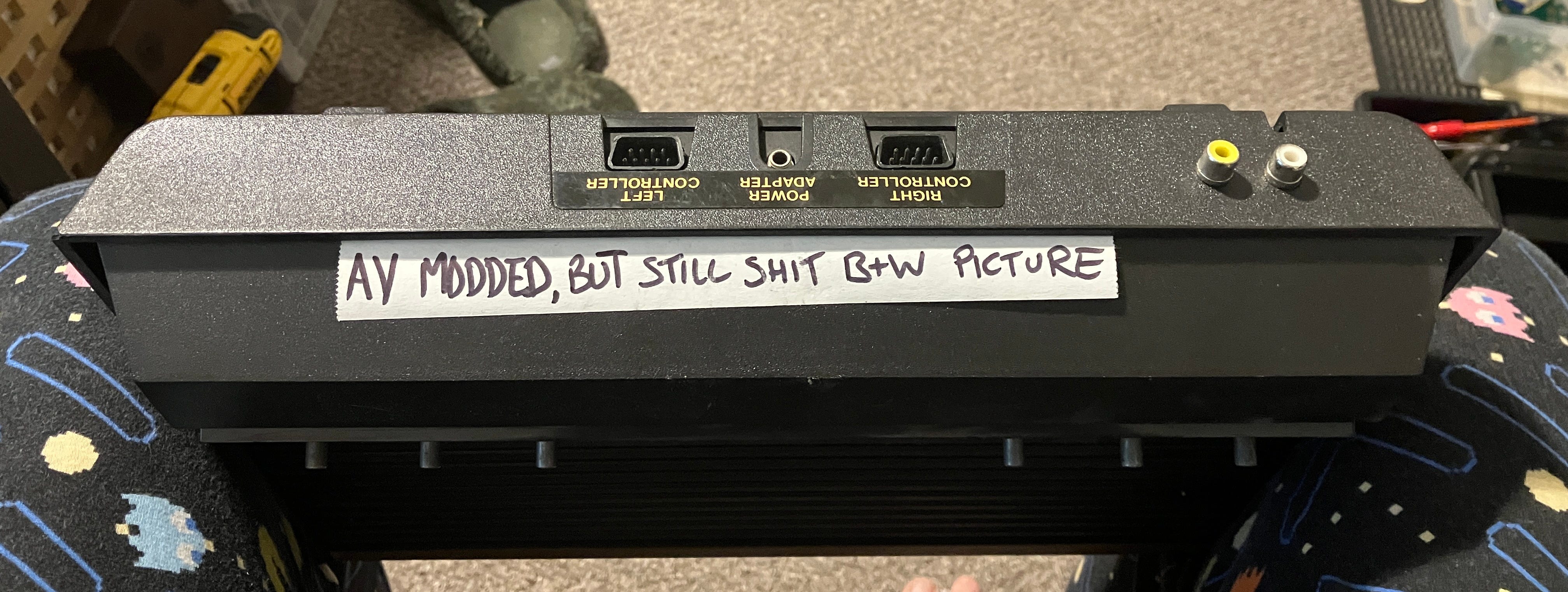
(Video output requiring some attention)
Apologies for Bobbi’s label, but it kinda says it all.
Yes, they are my Pac Man PJ bottoms. I roll to bedtime in style…
Let’s get this poor old thing opened up and see what’s what.
This was the mod that was in there. I haven’t seen one with a chip on it before. It also took some of the points from the power / switch PCB rather than the main board.
I removed the old mod and replaced it with one of mine, which I know are good. I powered the unit on and couldn’t get it going. I checked out the voltage regulator, as they are usually the first port of call for failures. It wasn’t generating a good +5VDC, so I renewed it and gave the heat sink plate a bit of a buffing as well as some new heat sink compound (probably the wrong amount)


I also replaced the two capacitors on the power / switch PCB as they weren’t in spec. I think they are voltage smoothing caps, so this will help along with the new voltage regulator. The machine still wasn’t coming on, so I chucked out the power supply I was using and injected a good clean voltage from my bench power supply into the Atari. It then worked perfectly.
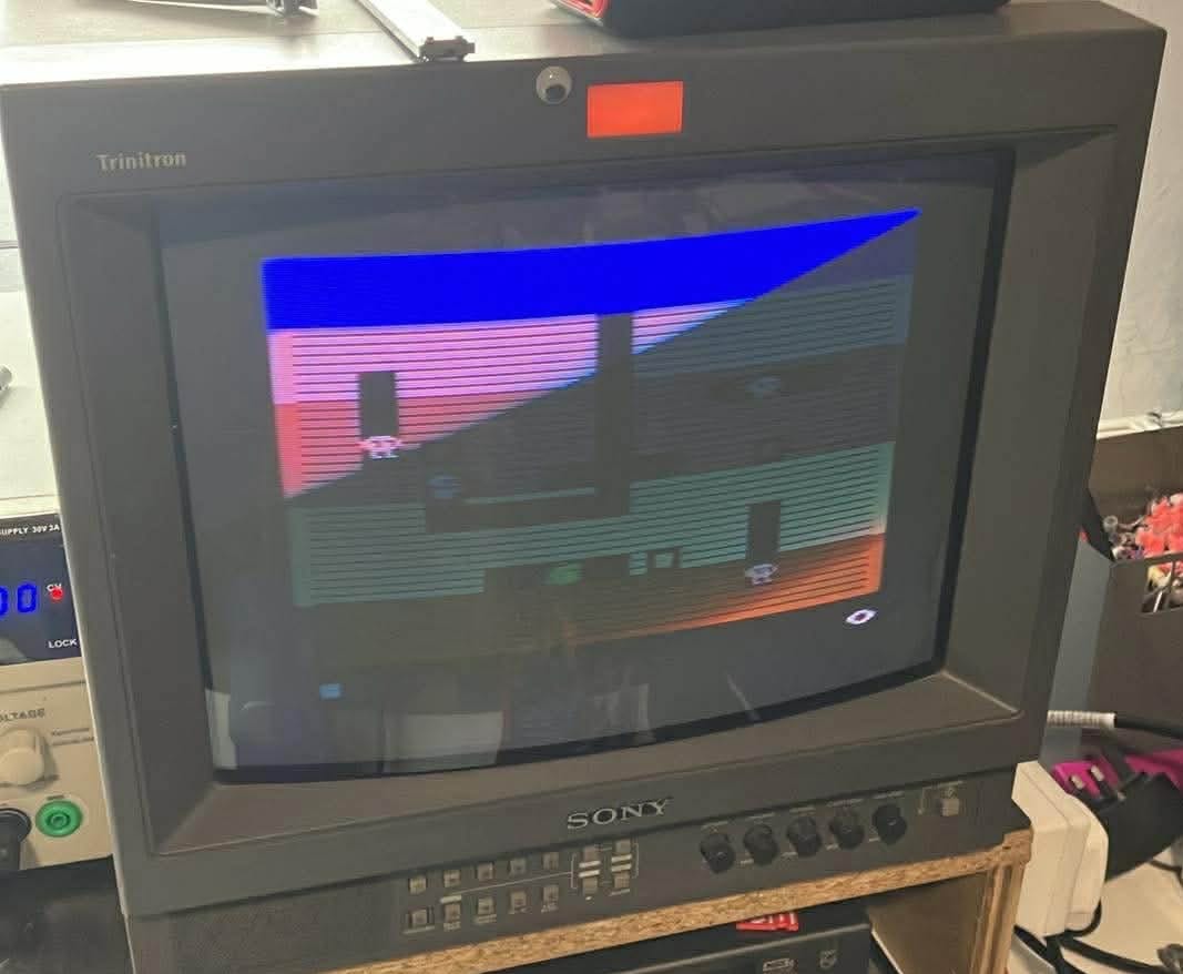
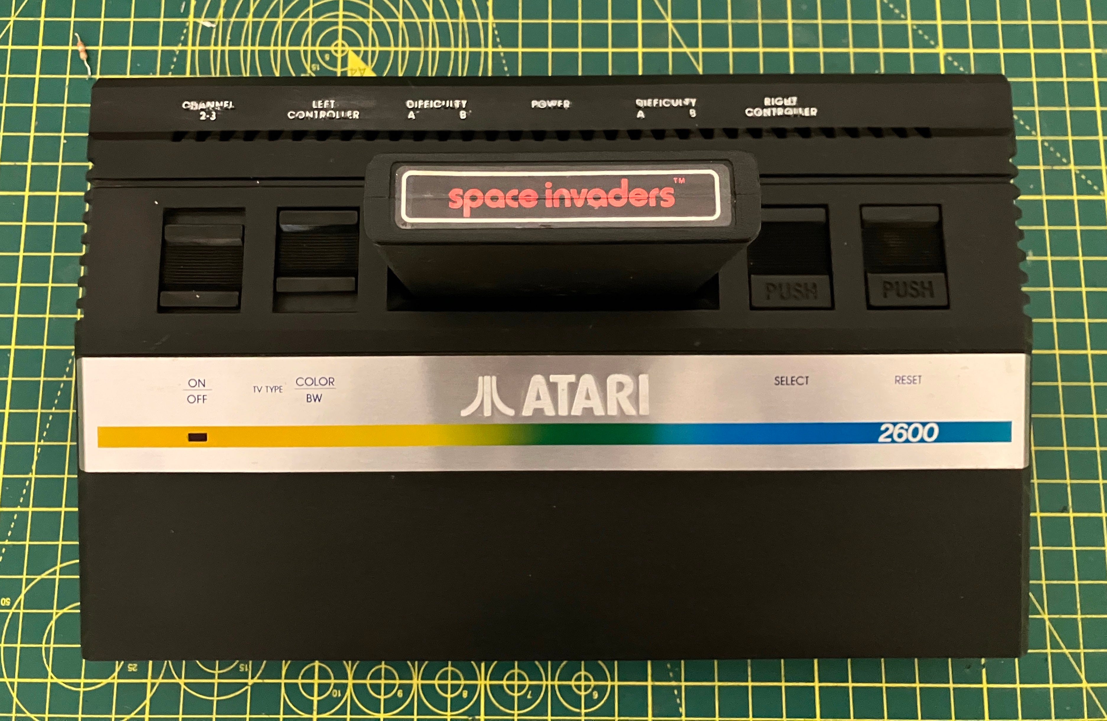
(As usual, a modern cell phone always captures a CRT image with a dirty great scan line across it). You can see that it isn’t a sh*t black and white picture, though…
I used my Uno SD cart to check with Space Invaders at first, as I know the colours of that game by heart. The invaders were all grey, with other colours not quite right. I worked it out that my Uno cart may have the NTSC version of the game. I used my original cart and the colours were correct, although the colour adjustment pot on the main board was intermittent, turning the image black and white. I’ll try cleaning it out with De-Oxit first and replace it if it still doesn’t function properly.
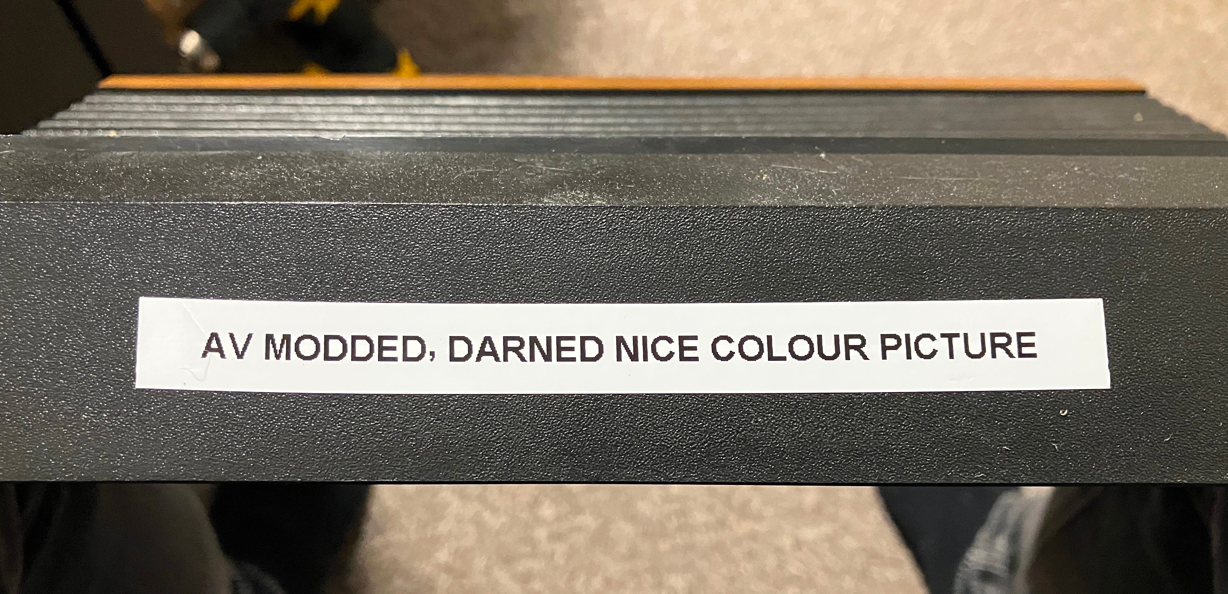
I have now replaced the original label.
NEXT!!!
Item Two - Atari 2600 Jr Fail #1
This poor thing only has RF sound and video output and wasn’t working with on the TVs Bobbi and I tested it on.
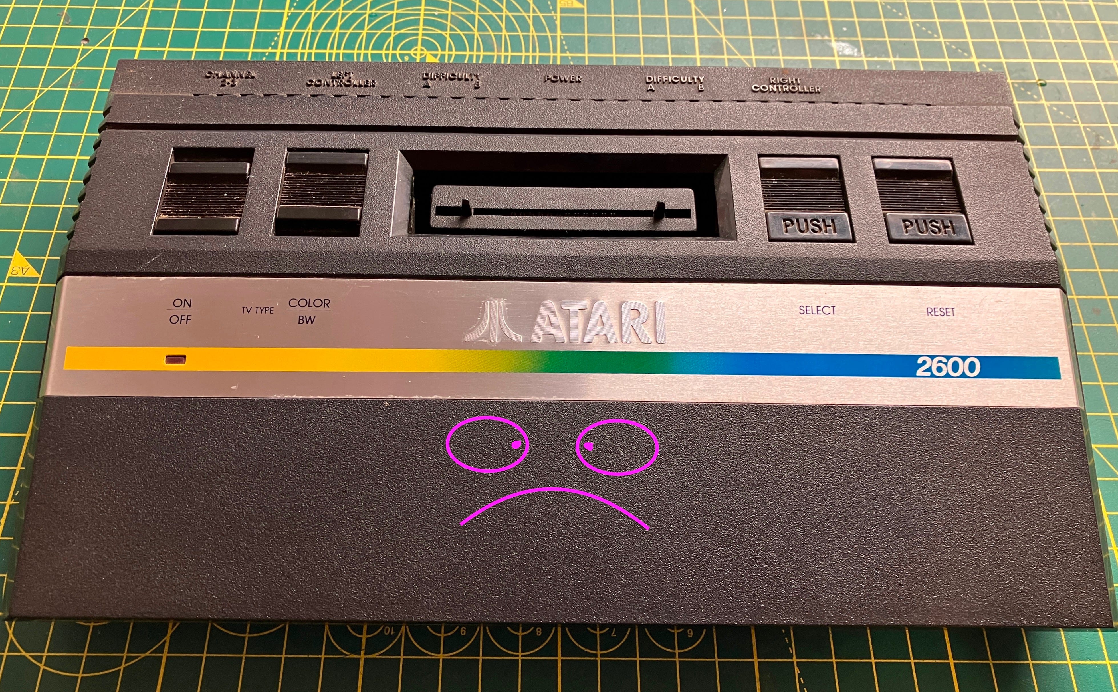
I know you’re all thinking that I’m some sort of graphic artist, but that Jr actually looked like that.
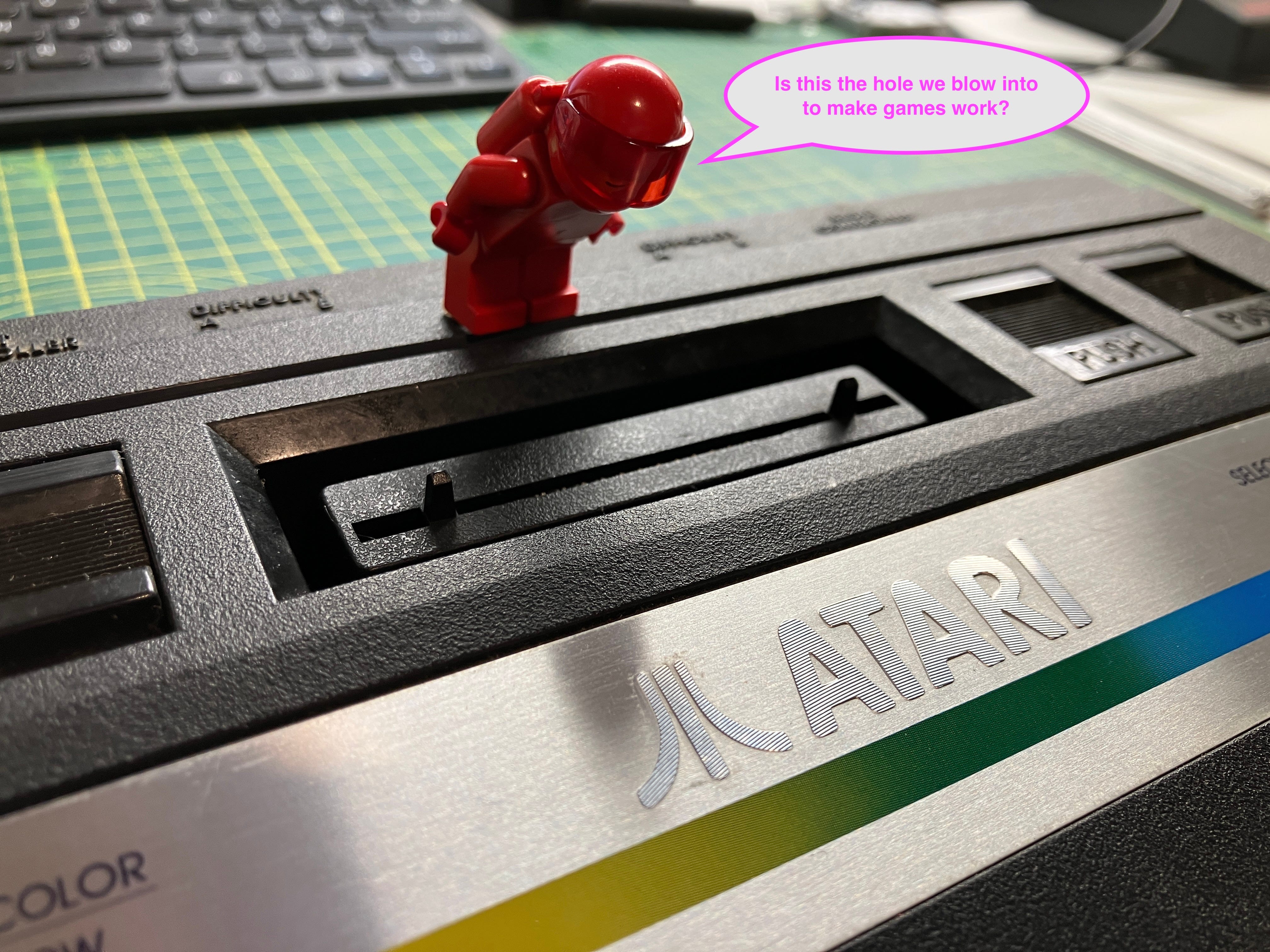
I had some help diagnosing the problem -
Took the thing apart and did the usual composite AV mod. I use my own PCBs (got them printed from Elecrow. Some sort of shared project). The pcbs need some SMD components soldering to them : a single 2.2K,3.3K,75ohm resistor and a transistor. You also need to remove a few parts from the Atari pcb and tap the video signal and power to the mod PCB. I always use the Teignmouth Software Blog guides
Sound is just picked up from a resistor point.
If you fancy just buying a pre made composite mod PCB, get them at TFW8B
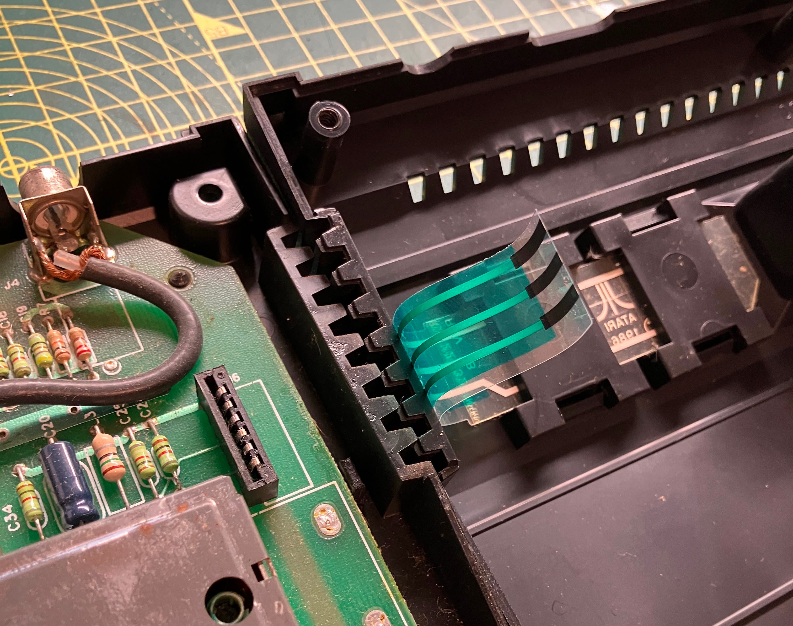
Be careful when tearing down your 2600 Jr, as this ribbon cable might get damaged, but it usually just pops apart. It’s a good strong ribbon.
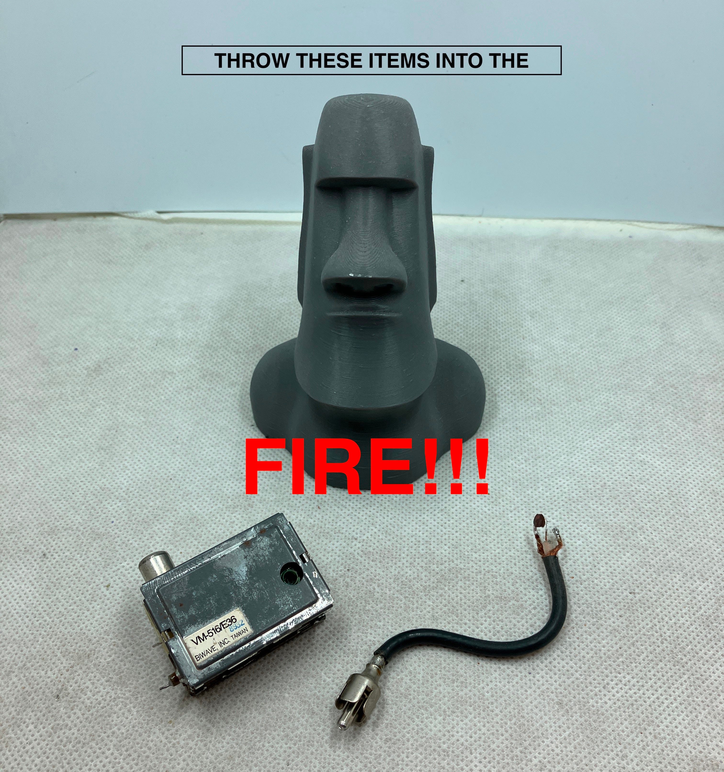
I absolutely love ripping RF gear out of old consoles to replace them with better video, but not as much as Easter Man does.
I drilled some small holes in the PCB and mounted an audio output component next to the newly modified video output. I filed out an appropriate hole in the back of the case for the new hole. I also gently ran over the text on the case with a silver paint pen to give the embossed letters some clarity.


The obligatory ‘finished!’ picture and, believe it or not, the picture hasn’t been altered in any way. I just used some ‘back to black’ car bumper polish on it and it turned out [smiley with sunglasses emoji]
More top tinkering going on here, with some fun consoles brought back to life, brighter and bolder than they ever were.