
NES Classic in a Handheld? (part 1 of 72*)
Say whaaat? *Not quite 72 parts...

Before I begin - I think I’m the only person to attempt this? I have only seen one person on YouTube try this, albeit with a bootleg NES classic and a composite LCD screen. They never finished it and it looks awful…
If you know of any other projects similar to this one, using a legit NES classic, please get in touch - I may be able to use them for inspiration (or blatant stealing of ideas)
Carry on, dear.
This is another project I started YEARS ago. I even jumped the gun and machined a pre-made enclosure (wrongly) and this is probably why I shelved the thing. Now I have been working on it and come up against a wall of problems, I can see why I dropped it like a hot rock…
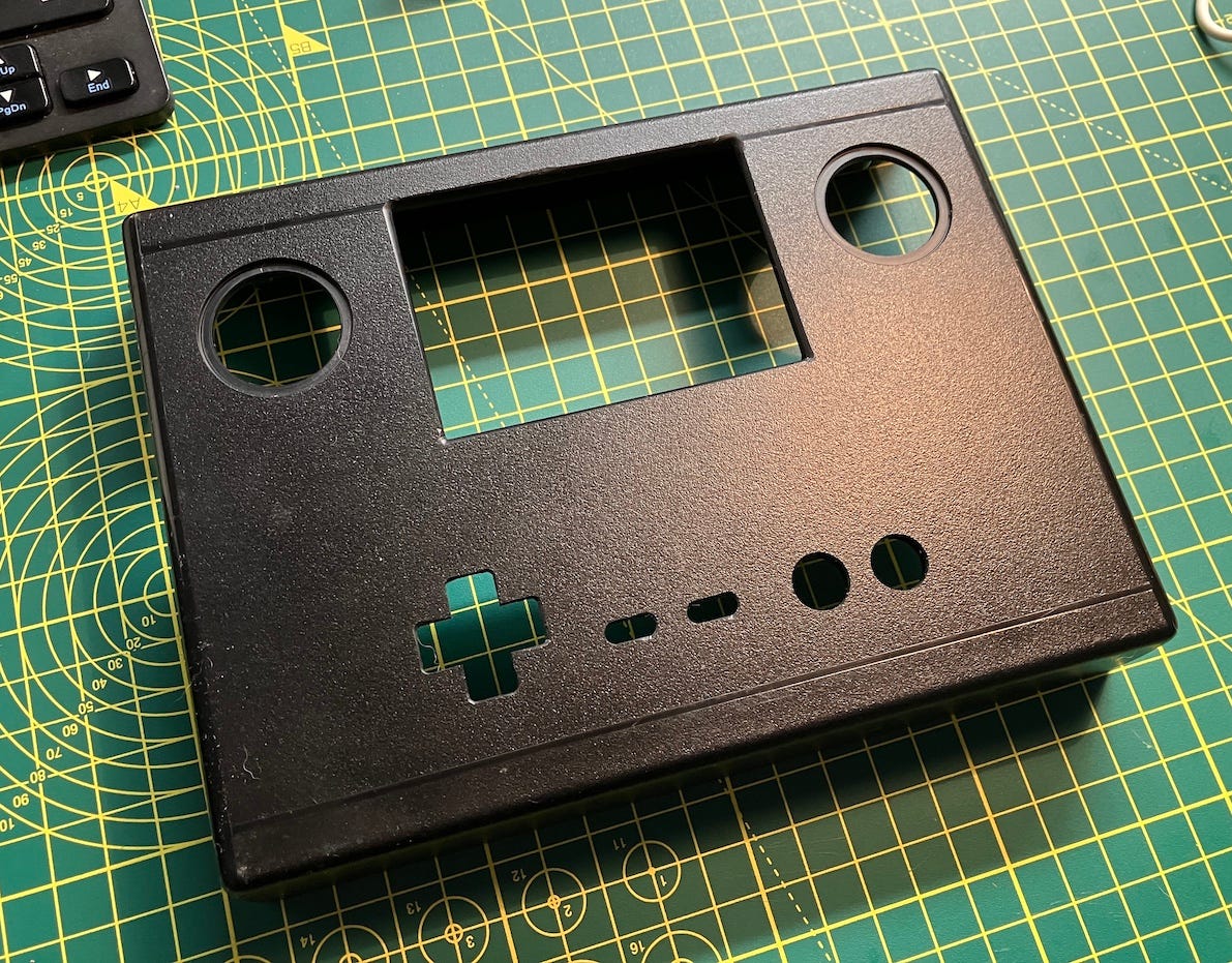
The main (huge) problem with the above picture is that the LCD screen fits in the rectangular aperture just fine, but the HDMI cable (and smaller bridge unit) goes in the back and can not physically fit in that box with the screen in that picture. Basically, that box is now scrap…
Mission (should I choose to accept)
I am going to attempt to put varying parts of the insides of a Nintendo NES Classic, an LCD screen, battery, controls, speakers and other required bits to make a New Classic HANDHELD gaming console. The case will be custom designed and made by me with the help of my 3D printer and CAD software, as usual.
Here are the parts & requirements of the project -
NES classic pcb
LCD Screen (has to be HDMI)
Controls
Speakers & volume control
Battery
Charging & powerboost pcb attached to Battery to give required +5v
2nd Controller Port
Case to house and attach the above parts
Clamps etc to hold parts internally
Checking out the ‘old’
I had no idea when returning to this project what other reasons, apart from the case may have steered me away from continuing all those years ago. My mind has a great way of blocking out these facts from me.
I attached the NES classic pcb to the LCD screen via a HDMI ‘bridge’ which came with the LCD screen. It is meant to attach the screen to a Raspberry Pi mini computer. It fits perfectly on top of most Pi computers (not the zero and pico)
I then powered both, individually with USB micro cables. I pressed the latching switch on the small pcb attached to the NES classic and it fired right up!
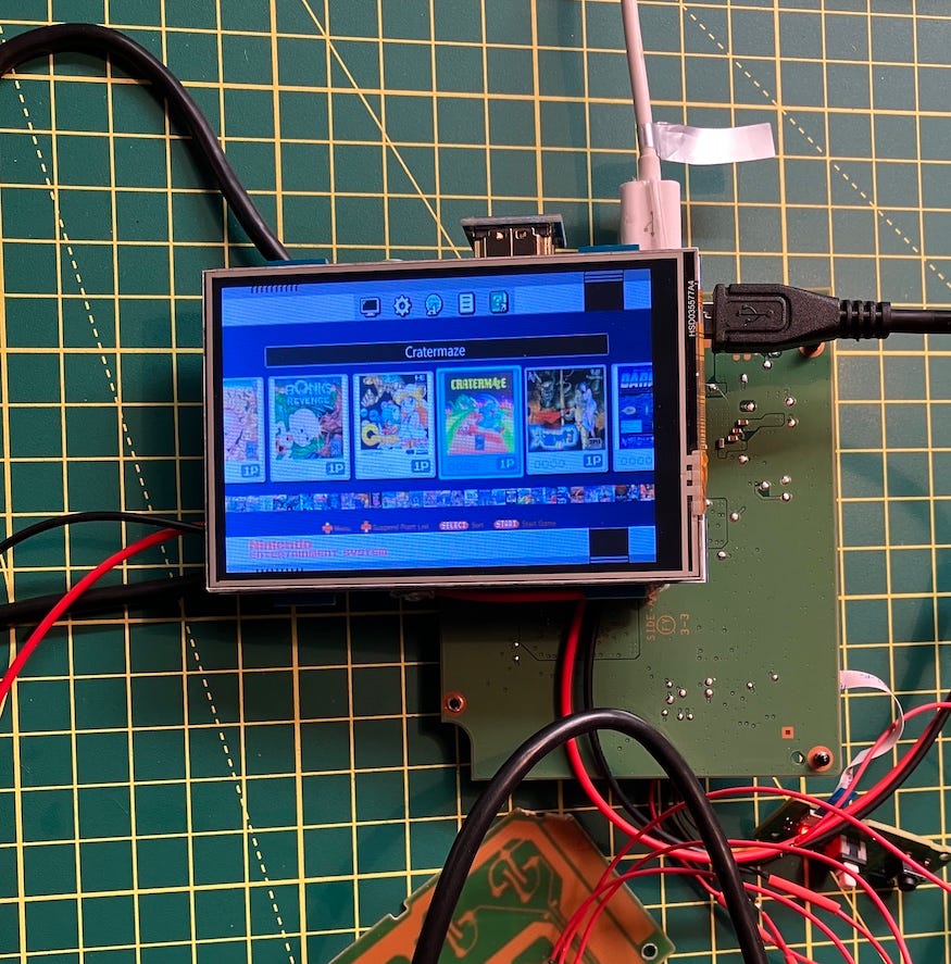
Eagle eyed readers might have noticed that there are a bunch of PC Engine games on the screen. Of course the unit has been soft modded already. Silly Rabbits!
Start of Design Work
I took the sizes of the original enclosure box I used (this was before I even had a 3D printer) and knocked up a very simple enclosure in two parts on my CAD software, as a 3D model. The top half would have the screen aperture, speaker holes, control cut outs, on/off controls and the ‘EXIT’ button for the system, which gets you back to the games menu. The inside of the top of the box would have screw posts to hold pcbs, controls, speakers, electronic components etc. The bottom half would hold the battery, battery charger and controls, the second controller port and various holes for inputs. The two parts would be married up with internal walls to line up the parts and six screw posts and counterbored holes for the screws.
At the time of writing, I am on ‘box_top_9’ and ‘box-bottom_5’. I have changed a LOT of things already, while trying not to waste too much time and 3D printing filament. WASTE IS BAD. I am using my cheapo yellow filament for development, that I bought only to make a Super Mario Star for our Christmas tree. I have so far, made two tops and one bottom. Things are looking ok for fitment etc so far. Wire management is going to be super important inside this box. I won’t be making the mistakes I made with the ‘tiny Invaders’ project. All electronic things are going to be able to be taken apart with ease using ‘JST’ style connectors. This will make closing the box with stuffed parts easier and tidier than everything hot glued down, although hot glue HAS been used already. NEAT AND TIDY.
There May Be Trouble Ahead
Already, I have had a few problems, or challenges as politicians like to call them. Whilst testing some things, I suddenly lost sound. After a frantic few minutes I worked out the problem. When I first plugged headphones into the port on the LCD screen, I got sound just fine. It sounded clear and reasonably loud on headphones (so, it’s gonna definitely need a volume control) At this point I had the LCD screen and NES classic pcb linked via a ribbon HDMI cable. I used this so I could separate the two parts to avoid any shorting of exposed pins while messing about with things. I discovered that when using the HDMI bridge, sound was gone. I have no idea why the bridge doesn’t have all the pins linked to each other as it should just be a 1:1 crossover between the plugs? I presume this bridge just doesn’t cover HDMI audio? The project cannot use the ribbon as the plug protrudes too far out the back of the screen for it to fit in the case. I have ordered another bridge and also a 90 degree ribbon cable. Hopefully one of those will work. Neither were advertised as carrying sound through the cable. You’d think that would be standard, right? Once I get the sound running with the screen correctly mounted I will need to tackle a volume control dial. This isn’t a simple thing to do. It requires a LOGARTHMIC pot for a start and I have no clue on what value of pot to use for the 2x 4ohm 2 watt speakers that are on their way to me. I may even need to use a small amp that will have its own volume control?
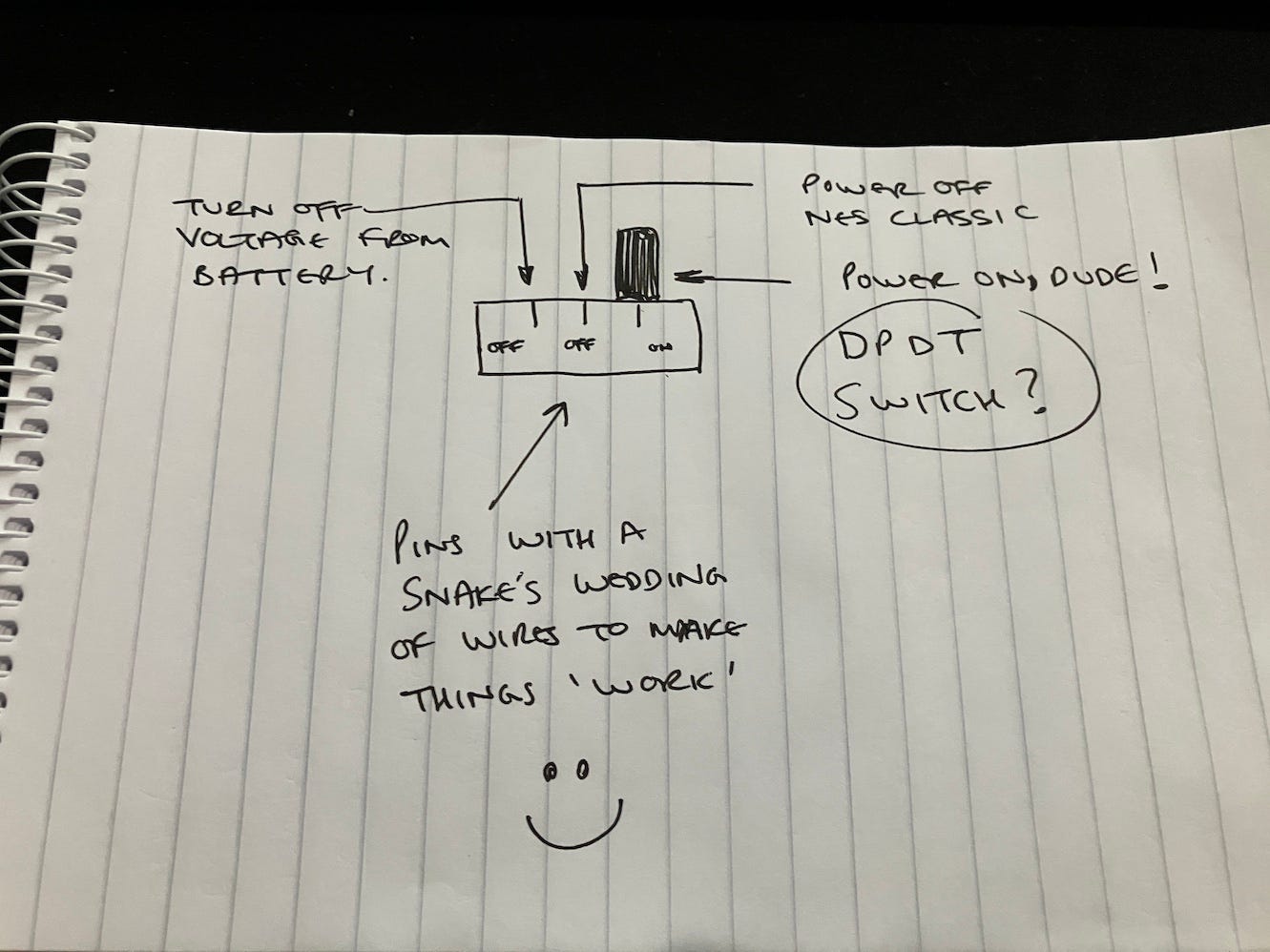
The way I have the battery, charging circuit and LCD screen and NES classic pcb wired up requires a main switch to turn the battery on and also a switch on a small daughter board for the NES classic to turn the machine on and also, more importantly power it off safely. As it’s basically a mini computer on a chip running Linux, it needs to be powered down via software with the switch. However, I maybe able to combine both together? Although, if the power is cut at the same time as the shutdown switch is pressed it won’t have power to do the shutdown. Oh no. I may well even have two on/off switches, but that just annoys me and I’m not clever enough to work out how to do this. If you are an electronics god or goddess and can help with this, please get in touch with me.
So far, (maybe) so good?
(YOU DECIDE)
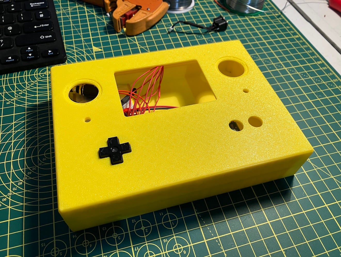
Here is the two case parts that actually snap together and look really good (although in a Mario Star yellow - final one will be black of course)
You can see the thing is an absolute unit, a brick, a lump if you may.
It’s EXACTLY how I want it to look. If you have followed Ben Heck over the years, this is the kind of thing he used to do and I’m a big fan of slightly janky looking DIY projects. I am certainly not a designer for Apple.
The fitment of the two parts is bang on. The D-pad you can see there is actually operational as well. You wouldn’t believe how hard it is to adequately recreate the feel of the pad and getting the correct spacings between the D-pad, rubber membrane and the controller PCB. I re-used the original controller pcb for the D-pad and will pad hack to the START / SELECT / B / A buttons. I have drawn up a very simple circuit board for the B & A buttons that will need to be milled out of copper circuit board - a first for me! The START & SELECT will be off the shelf momentary buttons. Probably from the ‘momentary buttons’ shelf, I’m guessing.
Final thoughts for this episode
I’m going to remove the other emulators off of this software hacked console. I just want it to be NES / Famicom games on here. I have many other platforms I can play PC Engine, Game Gear, Gameboy and other two button console games on. Let’s keep this thing simple, kids.
*EUREKA* moment.
I could use a switch that has three positions on it to power down and turn off power to the unit. The first movement from being powered on would be the ‘soft’ switch for the NES classic then the final movement of the switch to remove power. This in reverse would be electrical power on - console on. A winner!
For a brief moment, midway through reading, I got excited, thinking I might actually be able to help. Then I got to the end and your Eureka moment, which essentially was where I was going.
Great minds and all that...
I used this on something ages ago now, where the first switch just powered on the illumination, with the full switch powering on the psu.