
*tiny INVADERS
*well, pretty smol

Welcome Tinkerists!
This is another long overdue project that I started infinite moons ago. It re-caught my eye just recently and I thought it was high time the poor thing was seen through and finished off. Actually, redesigned and improved even!
Here is what it has been like for simply ages. Like, I mean a few years.
What You See Is What You Get (for now)
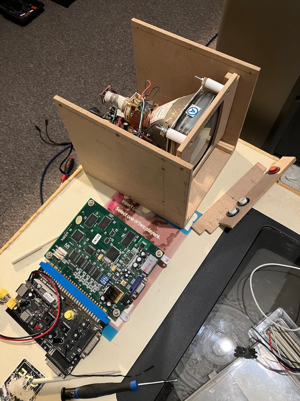
This picture consists of -
Black & white CRT ‘travel’ TV in a janky wooden case
60 in 1 JAMMA arcade pcb, set to just boot in to Space Invaders
Composite out supergun
Makeshift control panel. Left / right / fire
What needs to be done
Firstly, when starting up ancient old projects that you have ruthlessly cast aside for years, is testing. As you behaved so poorly to your project, the poor thing may have committed seppuku just to spite you. Maybe a cap will go *POOF* and release that pungent gas, or a raft of other electronic faults may decide to plague your day and really HARSH your MELLOW, man.
Ahem. On with the testing - The CRT TV needs +12v DC and the pcb needs +5v and +12v DC to work. The way I do this is power the collection of things with the highest voltage, in this case +12v and then use a voltage regulator to bring down the supply to a separate +5v. I like to use modern switching voltage regulators, as they are much more efficient and don’t get hot, and in turn, don’t need a heatsink. A standard ‘wall wart’ adjustable supply providing +12v with a positive inner of the connector will suffice, as would most standard type PSUs, just make sure the voltage and polarity are correct to what you want to power up.
This is the small ‘circuit’ that takes in the +12v and GND and distributes that voltage and ground to the TV (+12v) and the voltage regulator. Then +12v and +5v on to the game pcb. You wire +12v to a track of the copper strip board and Ground to a separate track. You then solder in the 3 legs of the voltage regulator (they are marked in a certain order) to Voltage in (+12v) / Ground / Voltage out (+5v) The voltage out gets it’s own track too. You can then spur off of the 2 voltages and Ground to the other components of this project.

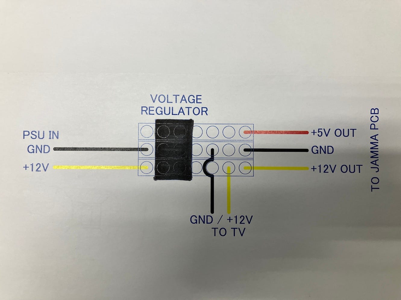
Here is a diagram of the circuit. I also forgot to draw in +5v and GND spurs to the video converter pcb.
I have soldered directly to the pcb, as this is going to be a dedicated game and if I get my way, the machine will be as small as possible, so won’t be able to take a mass of wires and a separate JAMMA connector and wires. Note - some JAMMA boards also require -5v, usually for odd ICs and sound hardware. The good old 60 in 1 doesn’t, which is good as converting positive voltage to negative voltage is quite a different process to just using a voltage regulator and *keep it quiet* - I don’t know how to do it???
Here is a *FREE* top tip when making / testing a project with a few different elements.
Nail everything down to a bit of old wood.
Or, more professionally - screw and secure with the appropriate parts all of your pieces so that nothing can short out to each other and you aren’t constantly knocking things off of your work bench. It doesn’t have to be anything fancy, just secure for now. It will all end up neatly attached in a handsome container by the end of this tinkering, don’t you worry.
Before we go on, I need to explain what a JAMMA supergun is and why the sparrow eyed (they have excellent vision, probably) of you can see there isn’t one in the picture.
A ‘Supergun’ isn’t a weapon at all, nor super. It’s just a name for a box or unboxed device that enables arcade pcbs to be powered by regular PC PSUs and played with regular joysticks and a TV rather than the need for a whole-ass arcade machine. I made my first one way back in about 2006 when I bought my very first arcade board, Tetris. There are many online guides and it’s quite an easy project to do. Especially handy when you have the arcade bug but haven’t got the room for an upright or cocktail cabinet.
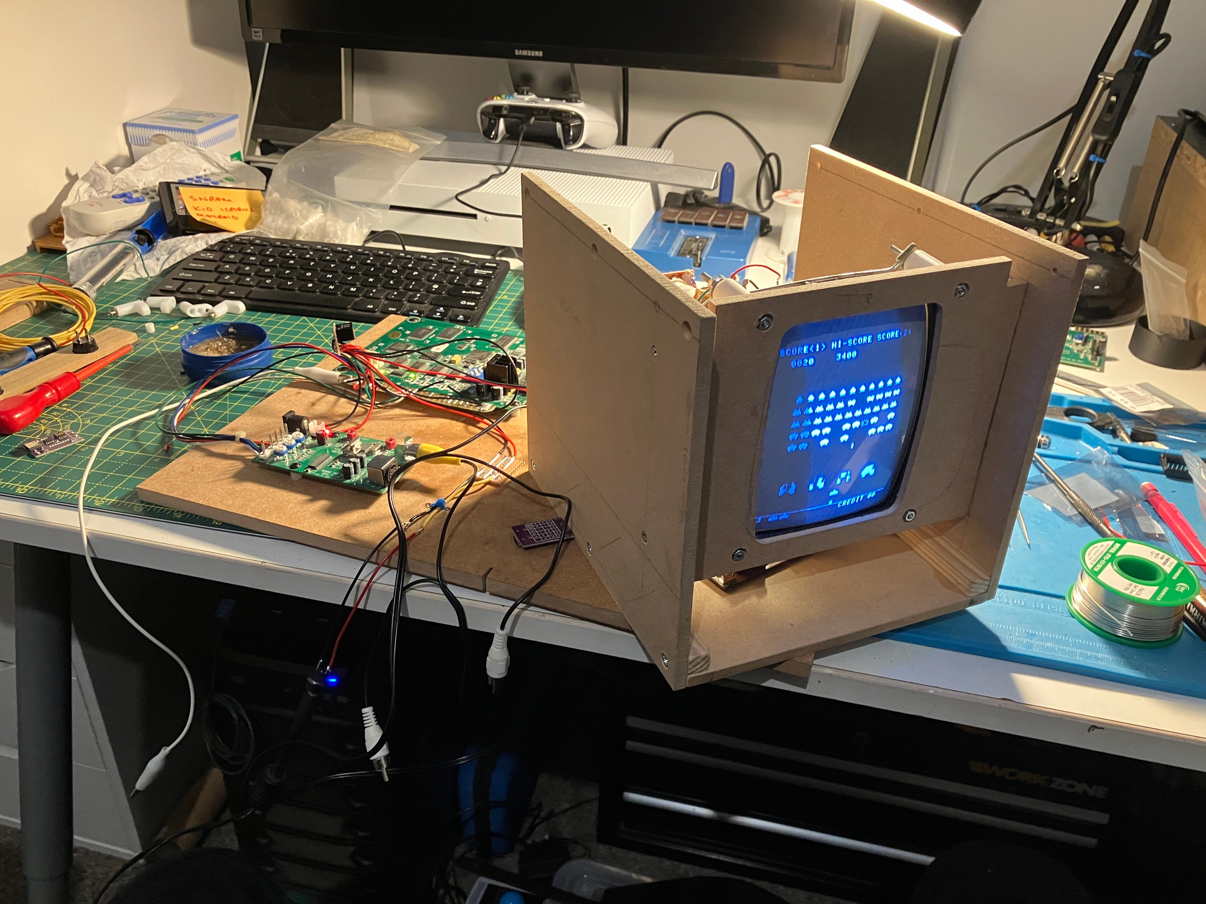
I have removed the need for the aforementioned supergun as it saves a lot of space. This particular game pcb can be wired directly to the controls, sound and display. The TV can only accept component video and the pcb can only output VGA or RGB. The small pcb on the left in the picture is a video converter. It takes in RGB and spits out component (or S-video on this one) As in the picture, this was a successful conversion and now the screen is overrun by Invaders from Space.
Redesign, redesign, redesign.
You can see that box, above, right? BOAK! (puke emoji) Whatever was I thinking back then?
I was in fact, thinking of making a cube shaped thing, but to be fair, it is simply horrid, darling.
I need a bartop shaped thing, but only just big enough to house the CRT and the various bits for it to function. It also needs to be ergonomic enough to play comfortably. If this comes off well enough, I may make others to go with it…
I set about the trash old structure and the CRT with my ruler and various bits of paper showing elaborate workings and algebraic calculations and along with my home CAD CAM software, came up with this -

I took a picture of my computer screen with a 1970’s film camera and scanned it into this blog. Well, it looks that way, but it was in fact a crappy picture of another screen with my iPhone. Deal with it Doris.
The sides will be 12mm thick wood effect MDF and every other panel will be 7mm black ash effect wood. Just like your auntie’s coffee table, bookshelf or tv unit from the 80s. I will also gussy up the screen bezel with a few effects too.
But that will be in part 2 (I haven’t made these parts yet and need to fire up the CNC wood router!)
I think you should stick with the original design. Looks solid to me..
Ah yes, black ash furniture, a staple feature in the 'Book of Dreams'.
Looking forward to see what the router creates. Mine is from EE and not very good at cutting wood..
Love ya!
Very nice!!